


The A4988 is a complete microstepping motor driver IC with built-in translator driving any stepper motor very easily . A4988 stepper motor driver is developed by Allegro Microsystems to help any one who wants to drive various stepper motor in their project.
Stepper motor is widely used for CNC and other automatic machinery projects. With the help of this A4988 stepper motor driver module, you can drive any stepper motor with just help of two pins of any microcontroller.
Today we will see in detail how this A4988 stepper motor driver can be interfaced with very popular Arduino board.
Features and Benefits of A4988 stepper motor driver
1. Low RDS(ON) outputs
2. Automatic current decay mode detection/selection
3. Mixed and Slow current decay modes
4. Synchronous rectification for low power dissipation
5. Internal UVLO
6. Crossover-current protection
7. 3.3 and 5 V compatible logic supply
8. Thermal shutdown circuitry
9. Short-to-ground protection
10. Shorted load protection
11. Five selectable step modes: full, 1/2, 1/4, 1/8, and 1/16
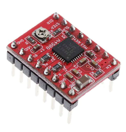
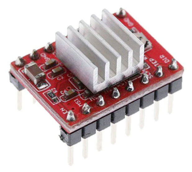
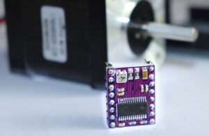
A4988 Stepper motor driver module
As this IC comes in 28 pin QFN package, it is becomes little bit difficult for hobbyist to use this IC. So this module with all necessary components and connections becomes very easy to use in our projects.

Interfacing A4988 stepper motor driver with microcontroller
Now, let us see how this module can be connected with any microcontroller.

Let us explore now how this module functions with its various pins.
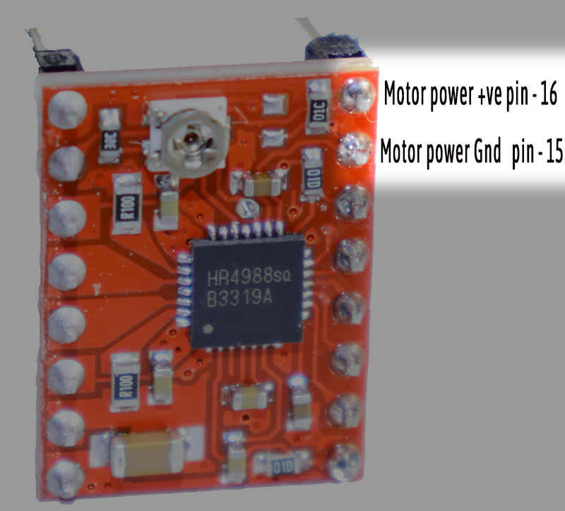
Power connection –
The module can be powered by DC supply up to 35 V and can handle up to 2A. These pins are highlighted in following pic. Generally the power will be between 8 and 35 Volt DC.
It is recommended to place a bulk power supply capacitor like 100 mfd near to power supply pins to smooth out current surges during driving of a stepper motor.
Please see that your power supply is rated at least 30% more than the maximum current that can be supplied to your stepper motor. Consult the manufacturer’s datasheet for this value.
Stepper motor connection
Each bipolar stepper motor generally has 4 connection wires that connects to two internal winding of the motor.

A typical bipolar stepper motor has following specifications –

Following figure shows the connection diagram of a stepper motor and also its working principle.
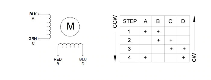
The stepper motor has to be connected to the A4988 driver module as follows.

Ok. After understanding the stepper motor connections, let us see how the power to A4988 stepper motor driver module is supplied.
Logic power supply
5 V DC has to be supplied to following pins to power the module.

After learning how the A4988 stepper motor driver can be connected to stepper motor, let us see how the motor can be controlled . This is done by properly handling the left hand side pins of the module.
Stepper motor control
Following pins show the most important part of the module as far as controlling the stepper motor is concerned – the Direction pin and Step pin.

Power control
Now let us understand power controlling pins. By this pins you can control the power to the module.
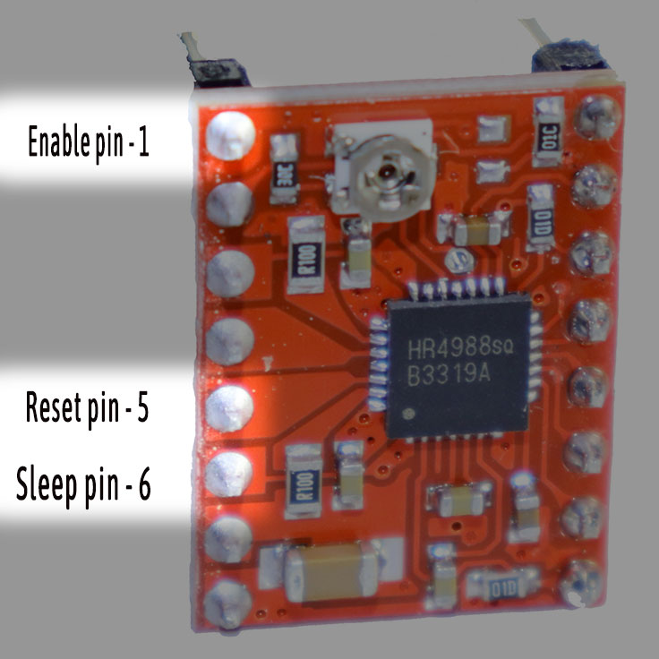
First pin is Enable pin. This is active low – means this module can be enabled by keeping this pin at low level. Internally this pin is pulled low so you can leave this pin floating to keep it enabled. But making this pin High will disable this module.
Fifth pin is Reset pin. It is also active low. By pulsing this pin low, you can place the stepper motor in Home position.
Sixth pin is Sleep pin. It is active low. By making this pin low makes this module sleep and the thus the power consumption can be reduced at lowest level.
Step selection
Most of the stepper motor has step angle of 1.8 degree. That means if you turn it for one step, the axis of the motor will turn 1.8 degree either clockwise or anticlockwise depending upon voltage level at Direction pin.
So for turning of one complete circle or one round will require such 200 steps. That means if you supply 200 pulses to the Step pin, the axis of motor will turn one full circle.
Now what if we want to turn the axis little bit finer… may be at 0.9 degree per step or may be half of that ? Fortunately , you can do it. Yes, the module can help you to have 1/2 th , 1/4 th, 1/8 th and 1/16 th steps per one pulse input.
It is called microstepping and it is a rather complex process energizing the coils with proper current levels. But by using this module it becomes very easy to choose how much steps you want stepper motor to have one revolution.
Just choose the appropriate pins and there you have it !

By setting appropriate logic levels, you can choose the size of one step or in other way – you can choose number of total steps for one complete revolution. It is as under –

All these three pins are pulled internally low, so if you keep these pins disconnected or floating, the step resolution will be 1 and total steps per revolution will be 200.
So now you know properties of each pin and how you can utilize them for controlling of any stepper motor.
Current setting
Let us take one final step to start using this A4988 Stepper motor driver module.
Torque capacity of each type of stepper motor is different depending upon their construction. This determines how much maximum load they can turn per revolution. Which, in turn depends on how much current can be applied to each of the coil – also called rated current of the motor.
A4988 stepper motor driver module has one preset provided to set this maximum current value that can be applied to connected stepper motor.

The voltage between the center point of this preset and the ground pin ( the pin number 9 ) of logic power supply ( VREF) , will determine the maximum current applied to the motor.
As per datasheet of A4988 IC,
The maximum value of current limiting is set by the selection of
RSx and the voltage at the VREF pin. The transconductance function
is approximated by the maximum value of current limiting,
ITripMAX (A), which is set by
ITripMAX = VREF / ( 8 * RS)
where RS is the resistance of the sense resistor (?) and VREF is
the input voltage on the REF pin (V).
So as far as our module is concerned, it uses 0.1 ohm resistors as sense resistor so to determine the VREF value we have to use following formula –
VREF = I ( max) * 0.8
One more fact, you have to keep in mind is that if you are using driver in full step mode, the current is limited to 70% of the maximum current limit, so accordingly you have to set the current limit almost 40% higher.
So for example if your stepper motor maximum current is 1A , then
VREF = 1 * 0.8 = 800mV
But if you are using full step mode, then
VREF = 1.4 * 0.8 = 1.12 V
So after applying 5 V to logic power supply, you can set the voltage at the preset at VREF as per your requirement with the help of multimeter and small screwdriver.
Interfacing A4988 stepper motor driver module with Arduino
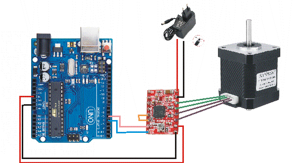
Now that we have understood all the functionality of the module, let us see how we can use this A4988 stepper motor driver with Arduino.
Connect Arduino UNO to the driver module as follow –
| Arduino pin | Module pin |
| +5V | 10 Digital supply |
| Gnd | 9 Gnd |
| 4 | 8 Direction |
| 5 | 7 Step |
Also connect 5th & 6th pin of module to each other. This will prevent the module not to go to Sleep mode.
Now connect the 12 V power supply to module and also connect 4 pin connector to 4 pins of module ( 11,12,13 & 14 ) as shown in above figure.
We keep pins MS1, MS2 & MS3 pins floating so that the module will drive the stepper motor in full step mode.
Arduino code
Following is the sketch of Arduino. Copy and upload to Arduino to see it functioning.
This sketch will rotate the stepper motor for one revolution clockwise and then one revolution counter clockwise. And this will go on repeating.
// Drive Stepper motor using A4988 stepper motor driver
// for more info visit arnin.in

// first define the pins
const int DirPin = 4;    // this pin defines direction CW or CCW
const int StepPin = 5;   // pulse this pin to move one step
const int SPR = 200;    // Steps per revolution

void setup()
{
	// Make pins as Outputs
	pinMode(StepPin, OUTPUT);
	pinMode(DirPin, OUTPUT);
}
void loop()
{
	// First let us rotate shaft clockwise
	digitalWrite(DirPin, HIGH);   // defines the direction to clockwise

	// Pulse the step pin
	for(int x = 0; x < SPR; x++)
	{
		digitalWrite(StepPin, HIGH);
		delayMicroseconds(1000);
		digitalWrite(StepPin, LOW);
		delayMicroseconds(1000);
	}
	delay(1000); // Short delay of one second

	// Now rotate shaft counterclockwise
	digitalWrite(DirPin, LOW);

	// Again pulse the step pin
	for(int x = 0; x < SPR; x++)
	{
		digitalWrite(StepPin, HIGH);
		delayMicroseconds(1000);
		digitalWrite(StepPin, LOW);
		delayMicroseconds(1000);
	}
	delay(1000); // Short delay of one second
}
Code explanation
The above code is self explanatory.
First we define the pins. Make them as Output pins.
Then we decide whether to turn CC or CCW. Accordingly we make the Direction pin High or Low.
Then we pulse the Step pin as per our requirement of revolutions. For example in above example we want one revolution so we multiply that count with 200 ( steps per revolution ) . So we have to provide 1 * 200 = 200 pulses through Step pin to make one revolution.
That is it. It is very easy to drive stepper motors using A4988 stepper motor driver module.
Please note that you can also drive stepper motor using A4988 Stepper motor driver module. Interested ? go to DRV8825 stepper motor driver with Arduino tutorial.
Try it and if you have any query, do comment below or you can also email to our support team at support@arnin.in to get answers.
Happy Stepping………………..


+ There are no comments
Add yours